In this article I will describe the various components inside the PC System unit and then provide appropriate
troubleshooting methods to isolate faults. In the first installment of this series we will cover ATX Power Supplies.
The ATX power supply unit or PSU, you might presume, supplies power to your PC but technically this is a misnomer.
If you pay your bill, the power company and the distribution network supplies the power! The PSU is actually a
power converter. It converts the alternating current (AC) supplied by the power company to direct current (DC) at all
the proper voltage levels needed by the components in your PC. It does this conversion by a process called "Switching",
rectification and filtering. You may have even heard the PSU referred to as a SMPS or Switch Mode Power Supply.

If you want to isolate a problem on your PC that is related to the PSU or related circuitry stick with me and read on!
If you would like general information on SMPS, there is a decent wiki and if you want to go even deeper into the design
of a SMPS, maybe check out the link on the right "(Internal) Troubleshooting Switch-Mode Power Supplies".

Please note that hazardous voltages and potential currents may exist in the PSU even when it is not
connected to the power line. There are capacitors inside that store power like a battery but at a much
higher level!!   All servicing should be performed by qualified personnel only!
An ATX PSU requires what is called a Power Supply or PSU On signal (Active low) to actually turn on. It gets this signal
from the motherboard via the green wire connected to pin 14.

An ATX PSU MAY BE DAMAGED if it is given an active PS On signal when there is no load on its output. I like to have a
motherboard and at least one hard disk drive connected. Floppy or CD drives will not help for this as they do not
continuously power their drive motors. Unless you have a very good reason or it is the last resort in troubleshooting,
I recommend to never plug in or apply power to an ATX PSU without a load!

A functional ATX PSU will always provide a +5v 720ma standby current via the purple wire to pin 9 on the mobo when it
is connected to the power line, and if it has its own on\off switch (usually labeled 0\1),  turned on or the "1" position.

Be aware that this standby current is also supplied to the PCI slots even when the PC is shutdown and damage
to the system may occur if this voltage is shorted by a dropped screw, Any wayward metallic object or If adapter
cards are manipulated. I recommend unplugging the PSU and waiting 30 seconds before working inside the system unit.


While we are on the subject, You must take proper precautions against ESD or electrostatic discharge. You have
experienced ESD if you ever walked across a rug and touched a doorknob and felt the Zap! ESD will destroy electronic
components even if the discharge voltage is so low you don't feel it!

Basic ESD precautions include discharging any static energy buildup on your body by touching a "Ground" such as the
PC case's unpainted metallic surfaces before touching any components in your PC or by wearing a grounded wriststrap.

NEVER, EVER use a wriststrap when working around any equipment that may have any electric potential or that is "Live"
connected to the line power.
Now with all the caveats and warnings out of the way lets get down into the good stuff. Below in figure 1 is a pinout of
the power connector on an ATX motherboard as viewed from above. We can use this as a reference in our discussion of
signals and voltages and also in measuring these values in the fault isolation section below.
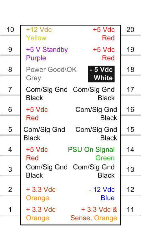
Fig.1 ATX 20 pin Power Connector
Important Note! On version 2 ATX Power Supplies there are four additional pins
The 2 additional pins above pin 10 are +12v yellow, and +3.3v orange
The 2 additional pins above (previously numbered) pin 20 are +5v red, and ground black
Where pin numbers are used in this article they refer to the 20 pin connector.

When you plug your PC in the wall outlet and turn on the switch on the power supply (If it has one), only two voltages
should be present on the Motherboard (mobo) connector. One is the +5V Standby current which can be measured on
pin 9 and should be, amazingly, + 5v. It's not hard to find as it is the only one that has a purple wire going to it.
This voltage, typically produced by a second power converter circuit in the PSU,  is used by the Wake On LAN feature
by network interfaces and some modems. More importantly, It is also used by the power control circuits on the mobo.

The second voltage you should see is the PSU ON signal. This can be found on pin 14 which has the only green wire
going to it. The initial state of this signal is set by the power supply by its connection to the 5v standby voltage via a
pull up resistor and has a typical value, at this point, of ~+3.5 volts or higher. This indicates a high or logic level 1.
This tells the PSU to remain off.

The PC's power on momentary switch is connected to the power control circuits (PCC) on the mobo. When you press
this button it is detected by the PCC. The PCC then checks to see if PC is already on, possibly by checking the
Power Good\OK signal which is generated by the PSU (Active High) or some other means. If the PC is already on, it sets
a flag that provides a signal to the BIOS and/or the OS. If the PCC finds the PC is not on, it interprets the power
button being pressed as a request to power up the PC and asserts the PSU On signal (Active Low).

The PSU senses the PSU On signal is now less than or equal to +0.8v which is a logic level 0 and starts enabling its
primary or main power converter circuitry. This is when you typically notice your fans and hard drives spin up.

When the PSU has completed enabling its primary converter and the +5 and +3.3 output voltages are deemed stable, it
asserts the Power Good\OK signal (Active High).

It is important to note that the + and - 12V supplies are normally not considered by the PSU before it asserts a
Power Good\OK signal! Understand that just because you have a Power Good\OK signal, does not guarantee +- 12V
is ok, although with a well designed PSU, there is a high probability that most of the PSU circuitry for these voltages is OK.

Some designs incorporate this "shortcut" assuming that if there was a total failure of the 12V circuitry, The 5V Standby
voltage would not be produced, therefore you would not even get to this point. The explanation gets deep and is beyond
the scope of this article. The bottom line is don't believe just because you have a Power Good\OK signal that
+- 12V is OK, especially under load. The unfortunate thing is that your PC may make that assumption!

Moving on, The PCC senses the Power Good\OK signal and in response, stops suppressing the CPU clock and
sends a reset pulse to the CPU chip, enabling it to start processing instructions. These instructions are part of your
system or graphic card BIOS and are typically located in an EEPROM or similar memory device.

The power up process is now complete.


Disclaimer: Please note that the above is a simplified description of the process. While it is logically correct, do not
consider this preceding text an exact engineering reference document. Also, I strongly recommend you do not try
ever opening or working on your system unit if you do not have extensive electronics training!
You are solely responsible regarding all risk and/or consequences. Please be careful.
In this section we will apply our knowledge to determine if a failing system has a faulty PSU. For most of the tests
you will be required to use a DMM or Digital Multi-Meter. You could also use an analog VOM or Volt-Ohm Meter.
Please follow all of the warnings listed in the previous sections. All disclaimers apply.

If you do not have a DMM or VOM, I will try to offer alternatives where I can.

We will start from the beginning and I will list all conditions you should see at each step. I will then explain what
may be causing certain conditions not to be true and recommend solution(s) or additional steps to perform. If all
conditions are proper for that step we will then move on to the next. I do realize that the following is quite long and
certain steps could be combined, but I felt that to educate the audience it was better this way.

If you are already experienced in troubleshooting electronic components and just want a brief guide that provides most
probable conclusions based on the voltage levels and signals, See my "Quick PSU Checkout Guide"
First make sure your system is getting power from a live outlet. You can test the outlet with your meter or just a
plain old lamp. If you are plugged into a power strip or APC be sure to test the exact outlet the PC's PSU will be
plugged into. Make sure the Power cord is seated fully in both the outlet and the PSU. Also make sure the input
voltage range selection switch on the PSU is set correctly.

With the PSU plugged in, if the PSU has an on/off switch, turn it to the on or 1 position. On your meter make sure it
is set to measure DC volts. If using a DMM use a range that allows 2 digits to the right of the decimal point.
Now inside the system unit, connect your black lead of your meter to one of the black wires on either a spare 4 pin
power connector or push it in one of common signal ground connections on the motherboards 20(or 24) pin power
connector. These are located on pins 3, 5, 7, 13, 15, 16, or 17.

Now connect your red lead of your meter to +5v Standby on pin 9 which has a purple wire on it. This should read within
5% of 5v. If you do not have a meter you can look to see if your motherboard and/or network connector have a LED that
is lit. Usually it is green. This method is much less accurate but without a meter, that the best we can do.
If this is lit or if your measured 5v standby is the correct value, unplug the PSU, reconnect the 20 pin power connector
into the mobo, reconnect the PSU to the live outlet, skip the following and go on to the next section.

If the standby voltage is not in spec or the led(s) are not lit, your PSU may be bad or the mobo may have a short. I
suggest removing all plug in cards including the graphics adapter and recheck the standby voltage. If is ok now,
suspect one of the cards.

If it is still not ok we can try one more test. Unplug the PSU from the live outlet and then disconnect the 20 Pin
connector from the motherboard. To do this locate the locking tab on the connector near pin 15 and press in the top
toward the connector while slightly pushing the socket in. Once it unlatches you can pull the socket out.

Reconnect your meter leads to ground and 5v standby (Pin 9). Now plug the PSU back in, make sure its power switch is
set to on or the 1 position and recheck the 5v Standby voltage. If it is still not within 5% of 5v, it is likely the PSU is bad.

If however, the standby voltage is now in spec, then either the PSU can't keep the voltage up under load or your mobo is
at fault. The latter is most likely at this point but if you have the means, try swapping out the PSU or testing it in another
system to be 100% sure it's not the cause. Mobos cost more and replacement is more involved so save that for last.
* Note! It is possible for both the PSU and Mobo to be bad!
Now that we have determined the 5v Standby voltage is ok, lets test the PSU On signal. First make sure the 5v standby
on pin 9 is still ok. Then connect your red lead to the PSU On signal on pin 14 which has a green wire going to it.
At this point it should be at a logic 1 state or above ~ +2.5 volts keeping the PSU's main PSU outputs off. If it is OK, Skip
the following and go on to the next step in the next section.

If the PSU On signal is not in a logic 1 state, the PSU should be fully enabled and you should have all the proper
voltages and the fans should be spinning! At this point that is irrelevant and will be moot if we follow the process.
What is important is to find out why this PSU On signal is not at the expected logic 1 state.

Possible causes are your PC's power on pushbutton, it's wires or your motherboard is bad. See if you can locate where
the PC's power on pushbutton is connected to the motherboard and disconnect it. You may need to consult your
motherboards documentation regarding this. It also may be labeled on the mobo silkscreen.

With it disconnected recheck the PSU On signal on pin 14. If it is now a logic 1, something is wrong with the PC's
power on pushbutton wires or momentary switch.

If it is still not a logic 1 your mobo or PSU is bad. Unplug the PSU from the live outlet and then disconnect the 20 Pin
connector from the motherboard. Reconnect your meter leads to ground and the PSU On signal (Pin 14). Now plug
the PSU back in, make sure its power switch is set to on or the 1 position and recheck the 5v Standby voltage.
If it is still ok, recheck the PSU On signal, If it is still not a logic 1 (~ 2.5v or higher) the PSU is bad.

If the PSU On signal is now a logic 1 (~ 2.5v or higher) your motherboard is bad.
If you have the means, try swapping out the PSU anyway or testing it in another system to be 100% sure it's not the
cause. Mobos cost more and replacement is more involved so save that for last.
We have now tested both the 5v Standby voltage, the PSU On signal and the circuitry that produces them.
We have either rectified any problems with them or found they are all OK. Now we will find out what happens when
we try and turn the PC on.

To make sure we are all on the same page here make sure the PSU's 20 pin connector is plugged securely into the
motherboard and recheck the +5v Standby on pin 9 which has a purple wire on it. This should read within 5% of 5v.
Also recheck the PSU On signal on pin 14 which has a green wire going to it. At this point it should be at a logic 1 state
or greater than ~ +2.5 volts keeping the PSU's main outputs off.

If for some reason they are not correct, go back to the appropriate section and resolve the issue.

Also at this point, none of the fans should be working and the +/- 5/12 and +3.3 voltages should read 0 volts.

While monitoring the PSU On signal on pin 14, Press the PC's power on pushbutton. You should see the PSU On signal
go from a logic level 1 to a logic level 0 which is typically less than 0.9v. If it does change state successfully, skip the
next paragraph and continue.

If it does not change value there is either a problem with the PC's power on pushbutton and/or its wires or the
motherboard is bad. Find out where the PC's power on pushbutton and wire connect to the mobo. You may need to
consult your motherboards documentation regarding this. It also may be labeled on the mobo silkscreen. Disconnect the
wire's connector from the motherboard. Turn off the PSU's power on switch to the off or 0 position or if it has none,
unplug the PSU from the live power outlet. Find out if the power on pushbutton is of the normally open or normally
closed type. You may find this information in the motherboards documentation. If it is normally open (Most Common),
jumper together the two pins where you removed the connector. If it is a normally closed type circuit, leave the pins
unjumpered. Now either turn the PSU back on or plug it back in. Recheck the PSU On signal on pin 14. If it is still
incorrect (logic level 1) you either chose the wrong type of power on circuit (Normally open or closed) or the
motherboard is bad.
If the PSU On signal is now correct at the logic level 0 state, the PC's power on pushbutton and/or its wires are bad.


Now that the PSU On signal is in the logic level 0 state, this provides the signal to the power supply to fully enable its
primary or main power conversion circuit. If your fan(s) come on and your hard drive spins up, the power on circuit
is functioning properly and +12v is present, Skip the following and go on to the next section.

If the fan on the CPU spins but the hard drive doesn't spin up then, the power on circuit is functioning properly, you
have 12v being produced by the PSU and might have a bad or mis-strapped(Jumpered) hard drive. Check the jumpers
on the hard drive. If the jumpers are correct and the power connector is plugged in securely, Try the hard drive on
another aux power cable. If it still doesn't spin up and you have the means, test it in another PC. If it spins up now,
you probably have a bad aux connector. Once you have this resolved, skip the following and go on to the next section.


If none of the fans and your hard drive doesn't spin up, you most likely do not have +12v. Check the +12v on pin 10
of the 20 pin PSU's 20 pin connector and on the yellow wires on the aux power cables. If you have power here,
something is wrong with your fans and/or hard drive. See the previous paragraph for some suggestions. Once you have
this resolved, skip the following and go on to the next section.

If you don't have +12v or it's not within +\- 5%, either the PSU is bad or something else is affecting the voltage. It
can be affected by the motherboard, Drives, and USB devices. Unplug the PSU from the line power and bring the
system down to minimum configuration removing all cards including graphic adapters, all USB devices and anything
using the aux power connectors except your main hard drive and recheck the +12v.
Note: Do NOT disconnect the fan on the CPU!

If you now get the +12v line to come up, isolate by replacing one component at a time until you find the cause. Once
you have this resolved and the system powers up OK, Congratulations! You are done.
If you still can't get the system to come up, skip the following and go on to the next section.

If you still do not have +12v, Either the PSU, The motherboard, or the hard drive are causing the problem. If you have
the means, test the hard drive in another PC. If you can't test it in another PC you can check the resistance across the
ground and +12v pins (2 or 3 Blk and 1 yellow) on the drives power connector. Unplug the drives power cable first!
If it reads less than 1K ohm (1,000 ohms), it is bad. If you can't test it in another PC and you don't have a meter,
You can try unplugging the power from it (the 4 pin connector) and then try starting up the PC while monitoring +12v.

Warning!I have seen and heard that powering up a system with only the motherboard connected may not provide
enough load on the PSU and can cause it to fail. While this is rare and usually only a problem with very low cost
PSU's, it is wise to be very careful. If you must try this method, try connecting a known good fan to one of the aux
power connectors and power up the PC just long enough to determine if you now get +12v and then shut it back down.

If you now have +12v and the CPU fan spins up, you have a bad hard drive. Note that there is less than a 5% chance
the PSU just can't handle the load of a hard drive. To be even more certain it is the drive, reconnect all the fans,
optical drives, floppy drive, adapter cards, and anything else you removed (Except the hard drive in question) and retest.
If all remains OK, The hard drive is bad. If the system won't try to come up with this extra load you have a failing PSU.

If you still can't get +12v, either the PSU is bad or the motherboard is killing the +12v. If you have the means, try
swapping out the PSU or testing it in another system to be 100% sure it's not the cause. Mobos cost more and
replacement is more involved so save that for last. * Note! It is possible for both the PSU and Mobo to be bad!

At this point replacing the PSU, The motherboard or both will resolve your issue. Another alternative is to seek
professional assistance. Consider our Live! Support service.
We have now either rectified any problems with or successfully tested the 5v Standby voltage, The +12v, The
PSU On signal and the circuitry that produces and responds to it. We have also determined the PSU On signal
is correctly enabling the PSU's main power conversion circuit.

To make sure we are all on the same page, make sure the PSU's 20 pin connector is plugged securely into the
motherboard and after turning the PC on by pressing its on pushbutton, recheck the +5v Standby on pin 9 and the
+12v on pin 10. They should read within 5% of the specified voltage. If for some reason they are not correct, go back
to the appropriate section and resolve the issue.

We should only have the hard drive connected to the aux power connectors. All fans (except CPU and PSU), optical
drives, floppy drives, USB devices are disconnected and all adapter cards including any graphics adapter are removed.

Sympton: The PC still is not powering up and booting but the CPU fan is spinning and the hard drive spins up.


First check the +5v on pins 4, 6, 19, and 20 on the PSU's 20 pin connector. Also check the +3.3v on pins 1, 2, and 11
and the -5 and -12v on pins 18 and 12 respectively. Note: On some systems the PSU may not supply the -5v. It is then
derived from the -12v on the motherboard.

These all should be within 5% of the specified voltage. If these voltages are OK, Skip the following and go on to the
next section.

If the voltages are not correct then the PSU may be bad. They also may be affected by the motherboard and the +5v can
be affected by the hard drive.

If the +5v is not correct and to eliminate the hard drive as a possibility, I will repeat a procedure from a previous section
with a slight modification.

If you have the means, test the hard drive in another PC. If you can't test it in another PC, you can check the resistance
across the ground and +5v pins (2 or 3 Blk and 4 red) on the drives power connector. Unplug its power cable first! If
it reads less than 1K ohm (1,000 ohms), it is bad. If you can't test it in another PC and you don't have a meter, You can
try unplugging the power from it (the 4 pin connector) and then try starting up the PC while monitoring +5v.

Warning!I have seen and heard that powering up a system with only the motherboard connected may not provide
enough load on the PSU and can cause it to fail. While this is rare and usually only a problem with very low cost PSU's,
it is wise to be very careful. If you must try this method, try connecting a known good fan to one of the aux power
connectors and power up the PC just long enough to determine if you now get +5 and then shut it back down.

If you now have +5v and the PC tries to boot, you have a bad hard drive. Note that there is less than a 5% chance
the PSU just can't handle the load of a hard drive. To be even more certain it is the drive, reconnect all the fans,
optical drives, floppy drives, adapter cards, and anything else you removed and retest. If all remains OK, you should
replace your hard drive. If the system won't stay up with this extra load you have a failing PSU.

If this fails to give you a good reading on the +-5, 3.3v, or -12v either the PSU is bad or the motherboard is killing the
voltages. If you have the means, try swapping out the PSU or testing it in another system to be 100% sure it's not the
cause. Mobos cost more and replacement is more involved so save that for last. * Note! It is possible for both the PSU
and Motherboard to be bad!

At this point replacing the PSU, The motherboard or both will resolve your issue. Another alternative is to seek
professional assistance. Consider our Live! Support service.
Ok, This is it. End of the line. We have now either rectified any problems with or successfully tested the 5v Standby
voltage, The +-12,+-5, and +3.3 voltages, The PSU On signal, and the circuitry that produces and responds to it.
We have also determined the PSU On signal is correctly enabling the PSU's main power conversion circuit.

There is only one item left to address, from a PSU standpoint, that could be keeping the PC from starting the boot
process and that is the Power Good\OK signal. As noted earlier in this article, This signal is active high and goes
true when the +5 and +3.3 voltages are deemed stable. Please note that some PSU's may determine this more
accurately than others.

When the Power Good\OK signal is logic level 0, the "PCC" suppresses the clock signal from driving the CPU chip. It
is this clock signal that steps the CPU from instruction to instruction. When there is no clock, the CPU is inactive.
When the Power Good\OK signal goes high or logic level 1, The PCC stops suppressing the clock and initializes the
CPU by sending it a reset pulse.

Given the fact that all the PSU output voltages are in spec, we should have a high, logic level 1 Power Good\OK signal.
Measure this on pin 8 of the 20 pin PSU connector on the motherboard that has the only gray wire going to it.

If it is low or logic level 0 The PSU is most likely bad unless the motherboard is pulling it down which could cause the
pull up resistor in the PSU to burn out also.

If you have the means, try swapping out the PSU or testing it in another system to be 100% sure it's not the cause.
Mobos cost more and replacement is more involved so save that for last. * Note! It is possible for both the PSU
and Motherboard to be bad!

At this point replacing the PSU, The motherboard or both will resolve your issue. Another alternative is to seek
professional assistance. Consider our Live! Support service.

If the Power Good\OK signal is, however, high or logic level 1 (2.5v or higher) and all the aforementioned voltages
and signals are correct, you can conclude your PSU is good and not the cause of your issue. Suspect the motherboard.


This is a quite long and detailed troubleshooting procedure but my aim was also to explain why we perform certain tests
and what conclusions we can then reach. I also discussed PSU and Motherboard related circuitry design.
If you found this page useful, consider linking to it.
Just copy (mark then ctrl-c) and past into your website.
This is how this link will look: Troubleshooting ATX Power Supplies
Version 1.0 Copyright © 2007-2008 www.AITechSolutions.net. All rights reserved. Terms of Use